Specifications
Height & Weight
- Height: 1.2 m
- Weight (target): < 40 kg (including battery)
Degrees of Freedom
- Total: 26 DOF
- Legs: 6 DOF × 2 (hip: yaw/pitch/roll, knee: pitch, ankle: pitch/roll)
- Arms: 5 DOF × 2 (shoulder: yaw/pitch/roll, elbow: pitch, wrist: pitch/roll)
- Torso: 2 DOF (yaw, pitch)
- Head: 2 DOF (yaw, pitch)
Kinematics (Human-Inspired Ranges)
Legs
- Hip: yaw ±45, pitch +120/−30, roll ±45
- Knee: 0→135°
- Ankle: pitch +45/−20, roll ±20
Arms
- Shoulder: yaw ±90, pitch +180/−60, roll ±90
- Elbow: 0→145°
- Wrist: pitch ±75, roll ±85
Torso
- Yaw ±45, Pitch ±30
Head/Neck
- Yaw ±80, Pitch +50/−40
Actuation
The robot uses ENCOS integrated joint modules, combining BLDC motors, planetary reducers, dual encoders, and servo drivers.
Upper Body
Specifications for the upper body actuators (arms, torso, head) are in progress and will be documented as the design matures.
Lower Body
The lower body actuators are defined and validated.
| Joint | Model | Voltage | Gear Ratio | Rated Torque | Peak Torque | Rated Speed |
|---|---|---|---|---|---|---|
| Hip — Flexion | EC-A6416-P2-25 | 48 V | 25:1 | 40 Nm | 120 Nm | 107 RPM |
| Hip — Abduction | EC-A5013-H17-100 | 48 V | 100:1 | 30 Nm | 90 Nm | 33 RPM |
| Hip — Rotation | EC-A3814-H14-107 | 48 V | 107:1 | 20 Nm | 60 Nm | 47 RPM |
| Knee | EC-A4315-P2-36 | 48 V | 36:1 | 25 Nm | 75 Nm | 109 RPM |
| Ankle | EC-A4310-P2-36 | 48 V | 36:1 | 12 Nm | 36 Nm | 75 RPM |
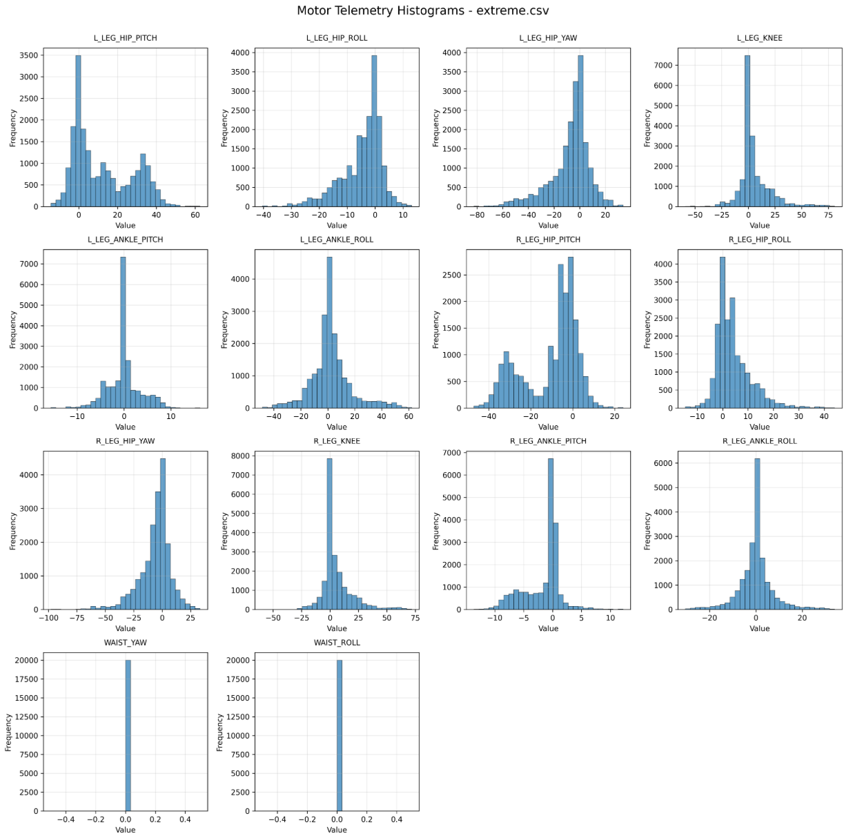
Empirical Torque Testing
We instrumented a UniTree G1 test rig to measure maximum torque capabilities across joints under extreme scenarios (e.g. push recovery, near-fall arrest). From these experiments, we derived operational torque envelopes — how much torque each joint can reliably deliver under load. This dataset guides safe actuator selection and control limits.
Alternate Actuator Options Explored
We evaluated actuator modules from MyActuator and CubeMars, but they failed to satisfy our form factor, torque, or rpm requirements for this design.
- MyActuator: myactuator.com (insufficient torque-to-size ratio)
- CubeMars: cubemars.com (didn’t meet required rpm and output specs)
We settled on ENCOS modules as the best match for our performance, integration, and size targets.
If you want, I can convert this entire Actuation section into a final polished version (without commentary) ready for direct inclusion in your spec sheet.
Power System
- Bus Voltage: 48 V DC
- Battery: 48 V Li-ion, 10 Ah (≈480 Wh)
- Pack: Swappable, integrated BMS with OV/UV, OC, short, and thermal protection
- Charging: External CC/CV charger, ~2 h full cycle
- Runtime: ~1–2 h mixed locomotion and manipulation
- Safety: E-stop relay disconnect on 48 V line
Sensors
- Vision: 4× ArduCam AR0234 global-shutter cameras (synchronized)
- Encoders: Dual encoders per ENCOS joint (motor + output) with ≤0.1° accuracy
- IMU: 9-axis (gyro, accel, mag) for balance and state estimation
- Audio: Seeed Studio ReSpeaker Mic Array v3.0 + onboard speaker
- Omitted by Design: No LiDAR, no foot sensing, no proximity sensors
More on our vision capabilities can be found here.
Control & Electronics
- Middleware: Menlo ROS
- Main Compute: Neocortex custom-developed platform for perception, planning, and control
- Actuator Network: CAN bus @ 1 Mbps to ENCOS modules
- Power Domains: 48 V actuator rail; 12–24 V logic/perception rail; isolated DC-DC; e-stop latching relay
- Audio: ReSpeaker Mic Array v3.0 + onboard speaker
System Architecture & Communication
The Asimov Robot uses a distributed control architecture. Actuators are grouped by limb and managed through local microcontrollers (MCUs), which communicate over a shared CAN bus.
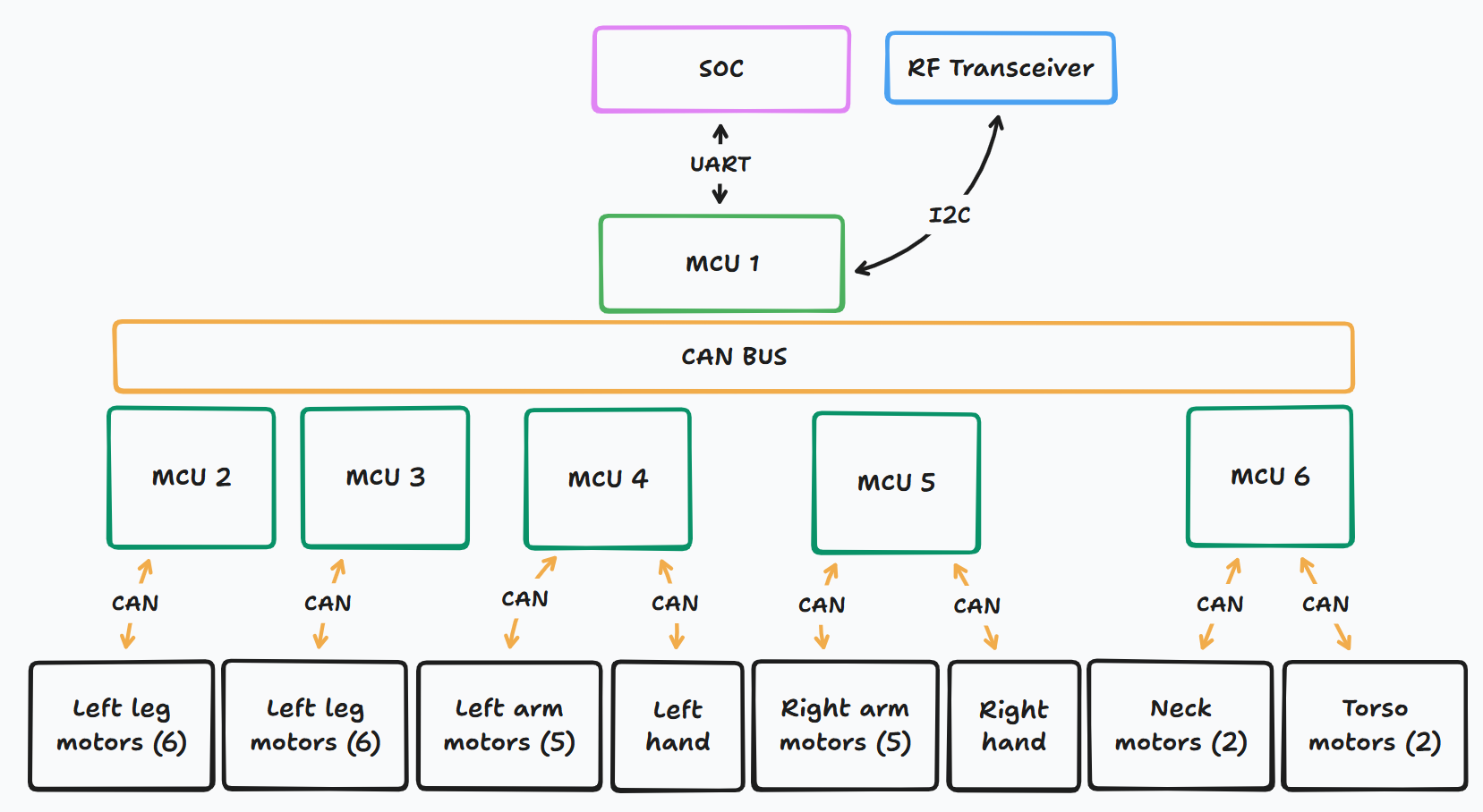
Architecture Overview
- Main Compute (SoC): NeoCrotex runs Menlo ROS, handling perception, planning, and high-level control.
- MCU 1: Serves as the gateway between the SoC and the CAN bus. Communication via UART from SoC, with an RF transceiver link available for wireless updates or monitoring.
- CAN Bus Backbone: Deterministic, real-time communication channel connecting all limb MCUs.
Limb-Level Control
Each MCU manages a group of actuators for one limb or subsystem:
- MCU 2 & MCU 3: Left leg (6 actuators each, split across hip, knee, ankle).
- MCU 4: Left arm (5 actuators) + left hand.
- MCU 5: Right arm (5 actuators) + right hand.
- MCU 6: Neck (2 actuators) + torso (2 actuators).
Communication Layers
- High-Level Commands: Motion planning and perception data flow from NeoCrotex (SoC) to MCU 1.
- Mid-Level Control: MCU 1 distributes commands over the CAN bus to limb MCUs.
- Low-Level Execution: Each limb MCU handles joint-level servo loops (position, velocity, torque) through ENCOS actuator drivers.
This layered design provides:
- Scalability: New limbs or subsystems can be added by attaching another MCU to the CAN bus.
- Fault Isolation: Failures remain localized to a single limb MCU.
- Real-Time Guarantees: CAN ensures deterministic timing for joint commands.
Construction Philosophy
- Complete Documentation: Mechanical, electronic, and software specifications available
- True Ownership: Full modifiability, repairability, and upgrade freedom
- Accessible Manufacturing: Off-the-shelf components + optimized 3D-printed parts
- Modularity: Arms, legs, torso, and head can be independently assembled or replaced
- Serviceability: Quick disassembly without specialized tools
- Collaborative Development: Comprehensive documentation for continuous improvement
Proportions
We defined the robot’s proportions using Winter, D. A. (2009). Biomechanics and Motor Control of Human Movement (4th ed.). John Wiley & Sons, p. 83.
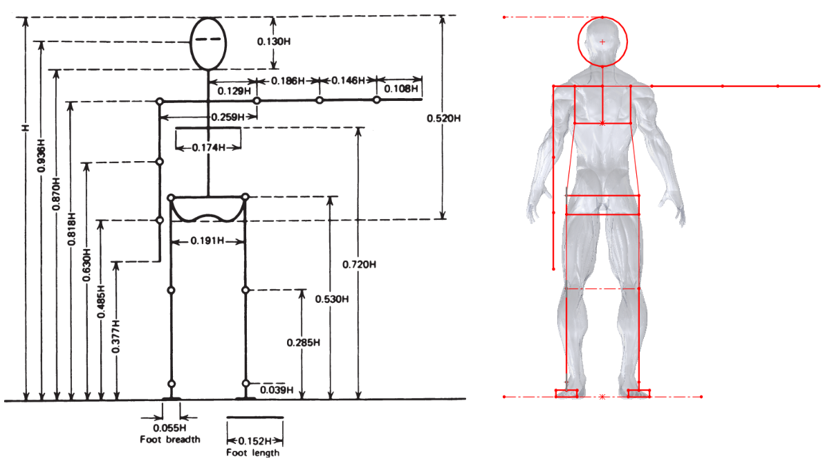
- A parametric model was created to adjust height and calculate dimensions joint-to-joint.
- This model was overlaid with a scaled human figure (1.2 m tall).
- The overlay confirmed correct joint alignment, resulting in a consistent anthropomorphic humanoid shape.